Convert Shell To Sheet Metal

Solidworks Solid To Sheet Metal Tutorial Convert To Sheet Metal Convert Shell To Sheet Metal Youtube

Solidworks Convert To Sheet Metal Cylinder Youtube

Inventor Sheet Metal Converting Solid Models Youtube
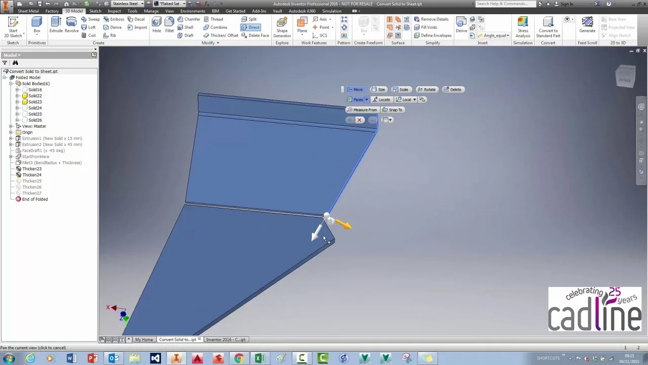
Inventor 2016 Converting A Solid To Sheet Metal An Alternative Method Cadline Community
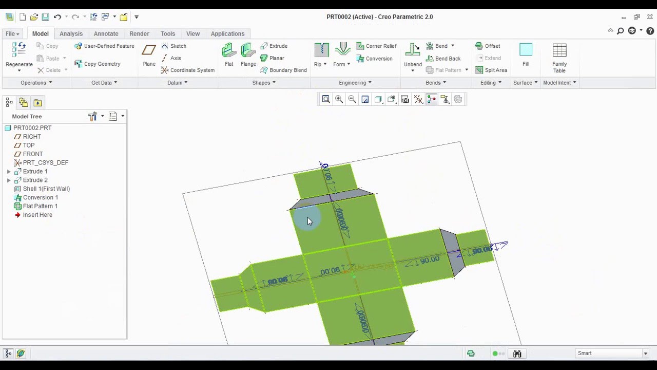
Solid To Sheet Metal Conversion In Creo 2 0 Youtube

Nx Sheetmetal Convert To Sheet Metal Flat Solid Hindi Urdu Youtube
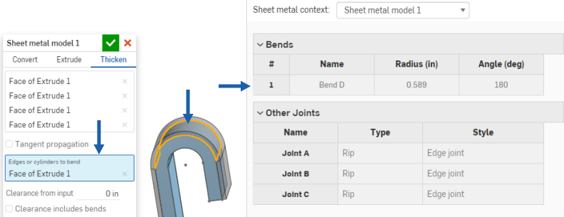
If an edge already has a fillet applied the radius of the fillet is used as the bend radius for the new sheet metal part.
Convert shell to sheet metal.

How Can I Convert This To Sheet Metal So That I Can Add Flanges And Flatten It Sheet Metal Canning Metal
Http Files Goengineer Com Docs Support Sheet 20metal 20bodies Pdf

How To Convert 3d Part Into Sheet Metal In Solidworks Youtube

How To Convert To Sheet Metal In Solidworks

Solidworks Convert Sheet Metal Vs Make Sheet Metal Part Youtube

Inventor 101 Sheet Metal Basics Autodesk Virtual Academy Youtube

Sheet Metal Prototype For Protection Shell Sheet Metal Fabrication Sheet Metal Metal Fabrication

Solidworks Tutorial 2 Ways To Flatten A Cylindrical Sheet Metal Part Youtube

How To Convert Standard Part To Sheet Metal Autodesk Inventor Youtube

Shell Mesh Definition In Solidworks Simulation

Inventor Shell 01 Youtube

Convert Solid Part To Sheet Metal Part In Solidworks To Improve Productivity Sheet Metal Sheet Metal Fabrication Metal Sheet Design

Solidworks Sheet Metal Tutorial Calculate Flat Form Of Elbow In Solidworks Youtube Sheet Metal Drawing Sheet Metal Sheet Metal Fabrication

Pin On Structure

Converting Models To Sheet Metal With Inventor Design Motion

Solidworks 2014 Converting A Solid Part To A Sheetmetal Part Youtube

Inventor 2020 Extrude Youtube

Solidworks Unlocking Properties In Sheet Metal Parts
Sheet Metal Model

Https Encrypted Tbn0 Gstatic Com Images Q Tbn 3aand9gcsdsmzyqjp2klfxfs8flb4pir6lxo9zdfkcpq Usqp Cau

Using The Rip Feature Solidworks Sheet Metal Tutorial Youtube

How To To Measure Length Of Metal Sheet To Make A Cylinder Of A Certain Daimeter Quora

Solidworks Tutorial Using The Jog Feature Lynda Com Youtube

Solidworks Sheet Metal Normal Cuts And Simplify Bends Youtube
Source : pinterest.com
